

The top 10 issues every system integrator and design engineer should understand
By Mike Ventola, CFPS – Industry Relations Director at Space Age Electronics

Smoke control system design pulls together more moving parts than almost any other life safety discipline in a modern building. It includes architecture, mechanical systems, electrical power, fire alarm, controls, emergency power, and building code requirements. When these systems work together, occupants gain additional time and safer conditions in which to evacuate or relocate. When you poorly coordinate the design, the problems often don’t surface until the building is occupied and an emergency occurs.
The key is understanding that smoke control is not simply a collection of fans, dampers, and control relays. It is an engineered life safety system with a specific design objective, a defined sequence of operation. On many projects smoke control is a required special inspection and acceptance testing.
Here are ten issues that deserve particular attention.
1. Start with the rational analysis
Before bidding, designing, or installing a smoke control system, find the Rational Analysis.
IBC Section 909 establishes the engineering framework for smoke control. Section 909.4 requires a rational analysis supporting the types of smoke control systems used, their methods of operation, supporting systems, and methods of construction. The analysis considers issues such as stack effect, fire temperature, wind, HVAC operation, climate, and system duration.
Anyone bidding the fire alarm, mechanical, or electrical portions of a project should consider reviewing the RA first.
Do not assume every smoke control system will look the same. A building may have a simple pressurization system, a complex atrium smoke management system, or several smoke control approaches. Mixed occupancies can make the coordination even more complicated.
The Rational Analysis establishes the design basis. It can identify smoke zones, equipment, airflow requirements, pressure relationships, operating conditions, and system interactions. Each can directly affect the fire alarm and controls contractor.
Practical lesson: If you bid a smoke control project ask for the Rational Analysis before determining the scope of work.
2. Know who is responsible for what
A functional smoke control system requires a team of professionals. Problems occur when everyone assumes someone else is responsible for a particular portion of the system.
The Owner establishes project objectives and may have additional requirements through the property manager, insurer, or corporate risk-management program.
The Architect coordinates the building design and establishes the responsibilities, documentation, compliance objectives, and timelines for the project team.
The Authority Having Jurisdiction (AHJ) reviews and enforces the applicable regulations. The AHJ has an important role in approving the final system.
The Life Safety Consultant (LSC) may be responsible for specialized life safety coordination, egress and system integration, and risk analysis. This is crucial for performance-based designs.
The MEP engineering team coordinates the mechanical, electrical, and plumbing systems. For smoke control, mechanical and electrical coordination is particularly important. The fans, dampers, controls, power sources, and wiring must operate together.
The Fire Protection Engineer (FPE) may develop the Rational Analysis. They may also coordinate fire protection, fire alarm detection and alarm (D&A), emergency control functions, firefighter smoke control panel operation, elevator functions, emergency communications, and other life safety systems.
Finally, the System Integrator turns those design requirements into an operating system. The important question is not simply “Who designed it?” It is:
Who is responsible for making each part of the system operate correctly with every other part of the system?

3. Understand the real purpose of smoke control
IBC Section 909 describes smoke control systems as systems intended to provide a tenable environment for the safe evacuation or relocation of occupants. The provisions are not intended to preserve contents, restore business operations, or assist firefighters with suppression and overhaul. However, a properly designed system may offer some of those benefits.
In simple terms, smoke control is about giving occupants a safer environment to travel through during the time needed to evacuate the affected area, or to relocate to another protected area.
Tenability refers to maintaining safe environmental conditions in the designated egress paths during the emergency for the required evacuation or relocation period. That period is not necessarily the same for every building, and it varies by occupancy type.
A high-rise residential building, an office building, an assembly occupancy, and a large atrium may have very different occupant loads, travel distances, and evacuation strategies. Partial evacuation can make the sequence even more complicated. The system may need to protect some occupants while allowing others to remain in designated areas.
Smoke control can also reduce smoke migration caused by pressure differences and stack effect. But the system’s performance must be based on the conditions established by the engineering analysis — not on a generic assumption that “more air movement is better.”
4. Understand the building construction type
The construction type provides important design criteria for how long you can expect a building’s structural integrity and critical systems to remain operational during a fire event.
The IBC identifies five basic construction types:
- Type I – Fire-Resistive
- Type II – Noncombustible
- Type III – Ordinary
- Type IV – Heavy Timber / Mass Timber
- Type V – Wood-Framed
Construction type alone does not answer whether there is requirement for a smoke control system. The occupancy, building configuration, and specific IBC provisions found in Chapters 3 and 4 determine where there are requirements for smoke control. However, construction type becomes extremely important when considering pathway survivability.
We may design a building with one- or two-hour fire-resistance-rated assemblies. That rating establishes an expected level of protection for the building elements. You cannot simply install critical smoke control wiring and equipment without considering what happens to those components when a fire affects the surrounding area.
Survivability references several approaches, including two-hour fire-rated circuit integrity cable, two-hour fire-rated cable systems, and two-hour fire-rated enclosures or protected areas for Level 2 and Level 3 pathway survivability. You can find pathway survivability levels in NFPA 72, Chapter 12. An important distinction to understand:
The evacuation period (typically in minutes) and the fire-resistance period (typically in hours) are not automatically the same thing.
Design the smoke control system and its supporting infrastructure to meet the survivability requirements that the applicable codes, standards, and project design establish. The design team cannot look at each system individually, it must look at them collectively. The entire operational function depends on all components surviving for a given period of time.
5. Egress time is not the same as fire resistance
This is one of the most important concepts for understanding the operational times for smoke control systems and other critical time constraints — evacuation of occupants, backup power, emergency lighting, fire service access elevators, and more.
Imagine a high-rise building in which the fire alarm system activates due to an automatic initiating device such as a smoke detector or waterflow switch. Occupant notification begins immediately, as does the smoke control sequence of operation. If the building remains on utility power, everything requiring power runs on its prescribed timelines.
Should emergency generator power start after a power loss, all required systems continue to run. However, a new timer starts for the one-hour fuel capacity of the generators. The fire alarm control unit (FACU) may still be on 120 VAC power. That means its 15-minute alarm timer has not even started yet. The building’s fire-resistive construction of one or two hours began when the alarm initiated, regardless of the size of the fire. The smoke control system operates according to its sequence of operation and must maintain a minimum of 20 minutes, or 1.5 times the evacuation time of the building.
As you can see, these systems do not have identical time requirements, start times, or durations.
The fire alarm system (FAS) must provide the required notification and perform its life safety functions. For voice evacuation, this is 24 hours on battery plus 15 minutes of alarm after those 24 hours. If the FACU also handles command and control for smoke control, the FACU and all related equipment must now comply with 20 minutes minimum, or 1.5 times the evacuation time — whichever is greater.
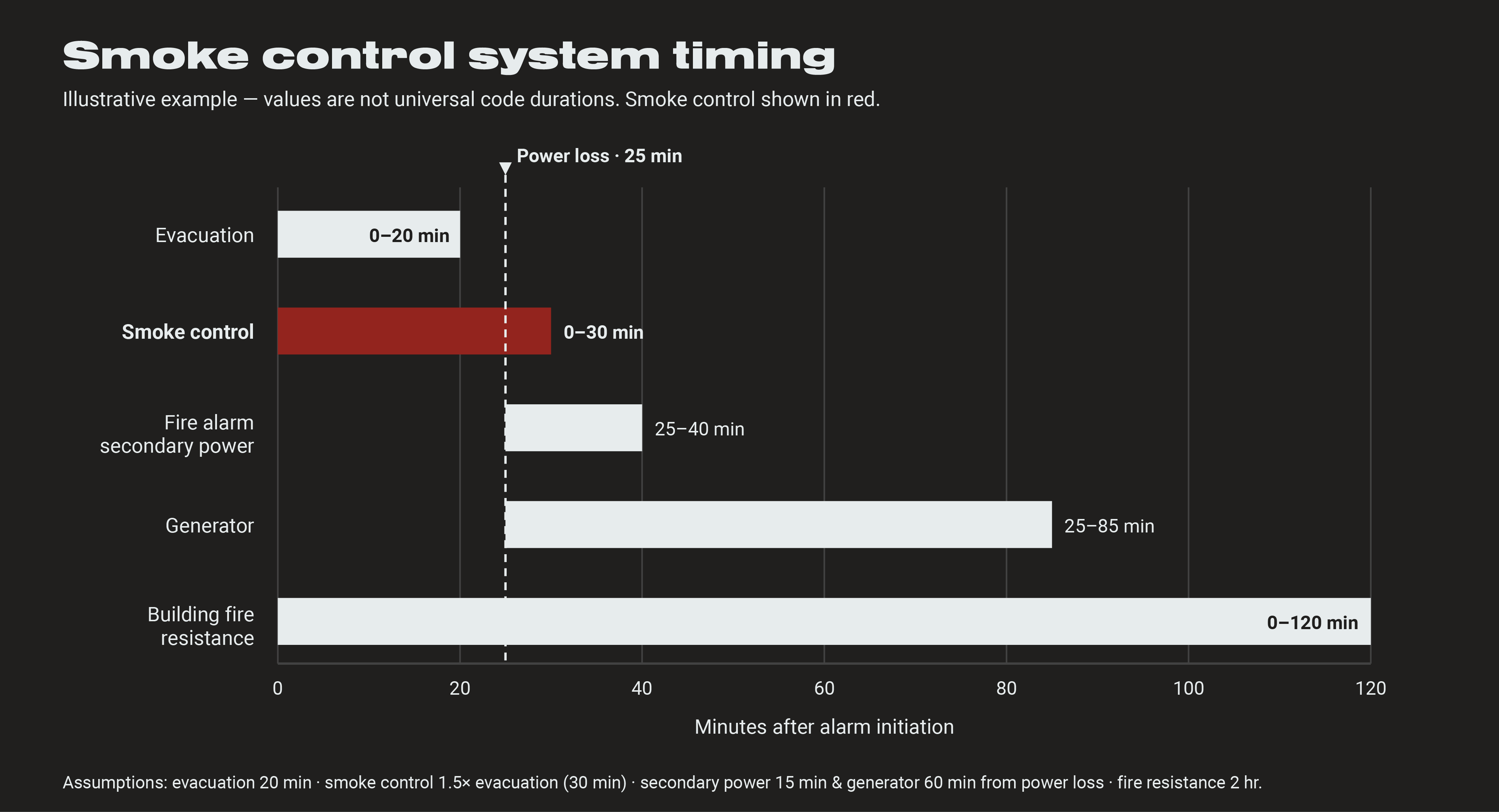
Illustrative timing assumptions:
- Alarm initiation: timer starts at 0 minutes.
- Full building evacuation: 20 minutes.
- Smoke control operation: 30 minutes, beginning at alarm initiation (= 1.5 × evacuation time).
- Normal power loss: occurs at 25 minutes.
- Fire alarm secondary power: 15-minute example period begins at normal power loss.
- Generator: 60-minute example period begins at normal power loss.
- Building fire resistance: 2-hour example period begins at alarm initiation.
Note: the 15-minute secondary-power period, 60-minute generator period, and 30-minute smoke-control duration are illustrative values for this timeline and should not present as universal code durations.
The emergency power system must support the loads assigned to it for the required duration — typically one hour of operation from a fuel or battery source. This timer starts only at utility power loss. Note that a generator can turn on and start the timer before any alarm is active in the building. Jurisdictional life safety codes deem the building unsafe and requires evacuation once there is no fuel and there is no additional power.
The fire-resistance-rated construction may provide a one- or two-hour rating. This applies to the structural integrity of the building and its systems.
The smoke control system has its own operational requirements established by the design and applicable code provisions.
For example, NFPA 92 requires smoke control system design to accommodate up to 15 minutes with components automatically performing their alarm-state functions upon restoration of power or under backup power sources after aa loss of normal power from the command-and-control computer, programmable logic controller (PLC), FACU, or similar.
The improper interpretation is saying the entire smoke control system only needs to survive or operate for 15 minutes. It is a specific computer operational-performance requirement, and it is a stand-alone performance criterion.
IBC 909 dictates the operational time of the smoke control system and all its related components to be a minimum of 20 minutes from initiation, or 1.5 times the evacuation time of all occupants.
The larger lesson: different life safety systems can have different performance durations that must coordinate those requirements rather than treat them as one universal time period.
6. Know which codes and standards apply
Smoke control sits at the intersection of several major codes and standards.
The International Building Code (IBC) and International Fire Code (IFC) establish many of the fundamental building and fire code requirements. IBC Chapter 9 is particularly important, with Section 909 addressing smoke control. The IFC parallels the IBC in chapter structure and may add requirements that many states prefer to enforce.
NFPA 92, Standard for Smoke Control Systems, provides detailed requirements for smoke control system design and operation, along with testing, inspection, and maintenance. NFPA 92 identifies requirements for smoke control equipment, ductwork, and electrical services, including the need for equipment to withstand the conditions anticipated by the design. Details on smoke control methods, design calculations, and the firefighter’s smoke control panel (FSCP) and its minimum requirements are all found in the body of the standard or its annexes.
NFPA 72, National Fire Alarm and Signaling Code, becomes particularly important where the fire alarm system interfaces with smoke control equipment. Chapter 21 addresses Emergency Control Functions, while Chapter 12 addresses pathways, pathway survivability, and circuit integrity. In many cases, when the FACU is also handling command and control for smoke control, NFPA 72 must expand beyond just D&A and comply with IBC, NFPA 92, and IFC where applicable.
Finally, NFPA 70, the National Electrical Code (NEC), establishes the electrical installation requirements. Articles 725, 728, and 760 can become especially important when dealing with control circuits, fire-resistive circuit protection, and fire alarm wiring — specifically Article 728 for fire-resistive cable systems and Article 760 for fire alarm systems.
The challenge is that no single code book tells the entire story. The system integrator needs to understand how these requirements overlap.
7. Understand the two basic smoke control system design approaches
A smoke control system does not really “control” smoke in the sense of making it disappear. Professionals generally create smoke control system design around two fundamental approaches: smoke containment and smoke management. (The details of both are in Chapter 3 of NFPA 92.)
NFPA 92 defines smoke containment as a method that uses mechanical equipment to produce pressure differences across smoke barriers. A common example is a pressurized stairwell which introduces outdoor air to maintain a pressure relationship that helps prevent smoke from entering the stairwell.
Smoke management, on the other hand, uses natural or mechanical systems to maintain a tenable environment in a means of egress, or to control and reduce smoke migration between spaces.
An atrium is a good example of where you may apply smoke management principles through the exhaust method, which may require makeup-air strategies to keep the smoke plume moving up and out of the structure.
It is important to note that a single building can use multiple approaches of containment or management. For example, a mixed-occupancy building might use pressurization to protect stairwells and smoke management to protect a large-volume atrium or other open space — typical in a convention center.
The system integrator needs to understand which approaches you are using, because it affects the sequence of operation, equipment, controls, monitoring, and testing, as well as the pathways that monitor and control all mechanical equipment.
8. Understand emergency control functions
An Emergency Control Function (ECF) is the interface between the fire alarm/signaling system and another building system that must respond to an emergency condition. Smoke control systems provide some of the clearest examples. These ECFs are not limited to the list below; other functions may be deemed necessary based on the occupancy use type.
The fire alarm system may initiate a control event signal that causes:
- A smoke control fan to start or stop
- A smoke damper to open or close
- A fire damper or smoke damper to change position
- An HVAC system to change operating mode
- A smoke control sequence to initiate, such as door openers or closers
- Equipment status to be monitored and annunciated
- Gas valves to shut off
- House lighting to come on, or background music to turn off
NFPA 72, Chapter 21 addresses these interfaces. Section 21.7 specifically addresses HVAC interfaces, including smoke dampers, fire dampers, and fan control. When these devices are connected to the fire alarm system, the associated detection and control interfaces are subject to integrity-monitoring requirements.
The location of the ECF and its related parts also matters. The interface device may be installed at or near the equipment it controls, rather than at the fire alarm panel or elsewhere in the building. Co-locating this interface serves several purposes related to supervision as well as test and inspection. This is where electrical coordination becomes critical.
Power-limited and non-power-limited circuits have different wiring requirements, and the separation requirements of NEC Article 725 must be met when ECF circuits are installed alongside other wiring.
The system integrator should therefore identify every ECF early in the project and determine:
Who provides the power? What device is being controlled? Where is the interface located? What voltages are involved? Who provides the interface? How is the circuit supervised? Who provides the wiring?
These questions should be answered and coordination with the trades should be completed before installation begins.
9. Don’t forget the monitored disconnects
Monitored disconnects are a classic example of a small component creating a major coordination problem. Disconnects are required per the NEC and IBC 909 for each piece of smoke-control-related mechanical equipment.
Smoke control equipment depends on electrical power. If a disconnect is turned off, the fire alarm system and/or firefighter smoke control system needs to know that the equipment is no longer available to perform its required function.
This is why monitoring the power status of critical smoke control equipment is so important. The problem on many projects is not the concept — it is scope responsibility.
The electrical contractor may install the disconnect and power wiring. The mechanical contractor may furnish the fans and dampers. The fire alarm contractor may be responsible for monitoring and controlling all the related mechanical equipment. The system integrator — often the fire alarm contractor — may be responsible for the overall sequence of operation.
But who provides the UL-listed power monitoring relay? Who wires it? Where and how does it terminate? What signals are displayed, and where? Is it a supervisory condition, a trouble condition, or another defined status condition? What happens at the firefighter smoke control panel when a power fault is detected?
If the construction documents do not clearly answer these questions, the issue can become a finger-pointing exercise during commissioning. If these required devices are not included at bid stage and are first identified when commissioning the system, the result is major project delays, significant change orders, and possibly system capacity limits that will not accommodate the additional points.
The solution is simple: identify monitored disconnects on the design documents and sequence of operations before the project reaches contract issuance, and well before the installation phase begins.
10. Treat the special inspection as part of the design, not the last test
The final smoke control test should never be considered just another fire alarm inspection.
IBC Section 909.18.8 requires smoke control systems to be tested by a special inspector, with testing that includes both construction-stage activities and final system verification. Final testing includes pressure-difference testing, flow measurements, and detection and control verification.
The special inspector also verifies the operation of the control sequences as outlined in the Rational Analysis, including operation from the firefighter’s smoke control panel (FSCP) and simulation of standby power conditions.
This is why the Rational Analysis (RA) is so important from the beginning. The RA is the first document everyone involved with the smoke control system will read and conform to within their given scope of work. For future reference, the RA belongs in a System Record Documents enclosure in the Fire Command Room to maintain access.
The final test is not simply asking:
“Does the fan turn on?” or “Did the damper open and close?”
It is asking whether the installed system performs according to the design that was engineered for the building and outlined in the RA. That can include:
- Correct fan operation
- Correct damper operation
- Correct airflow
- Correct pressure relationships
- Correct smoke zone operation
- Correct initiating devices
- Correct sequence of operation
- Correct firefighter’s control panel operation
- Correct emergency power operation
- Correct system status indication
- Correct wiring and control interfaces
- Correct disconnect reporting
NFPA 72’s treatment of Emergency Control Functions also reinforces the distinction between testing the fire alarm interface and testing the complete smoke control function. The fire alarm system may initiate the function, but the complete end-to-end performance of the smoke control system is governed by the applicable smoke control design and standards.
The special inspector becomes the independent check that the final installation reflects the RA’s design intent — for both code compliance and the engineered design. This special inspector is conducting a complete NFPA 4, Standard for Integrated Fire Protection and Life Safety System Testing, as it relates to the smoke control and life safety functions for the building.
Bringing it all together
The biggest mistake in smoke control system design — whether you are the system integrator or the design engineer — is to look at only one part of the system, and not the system in its entirety.
- The Rational Analysis establishes the engineering basis of design for code compliance.
- The project team establishes the responsibilities of individual trades.
- The building construction type and occupancy use type establish important design conditions for life safety and survivability.
- The egress strategy establishes the building’s means of egress and the time constraints for partial or full building evacuation.
- The IBC, IFC, NFPA 92, NFPA 72, and NFPA 70 establish the regulatory framework. Within them, the smoke containment or smoke management strategies found in NFPA 92 and the RA establish how the system is intended to work.
- The Emergency Control Functions connect the fire alarm system to the mechanical and electrical systems.
- The monitored disconnects and pathway survivability help ensure that critical equipment and controls remain available when they are needed.
- The special inspection and acceptance testing demonstrate whether the completed system performs as designed.
Smoke control is therefore best understood as an integrated life safety platform — not an isolated mechanical, electrical, or fire alarm system.
The system integrator’s goal is to understand the design intent well enough to coordinate every interface between the fire alarm system and the ECF. The design engineer has a different responsibility: creating documentation that spells out the intent clearly enough that every contractor understands what must be installed, controlled, monitored, and tested. When those two objectives meet, the building has a much better chance of having a smoke control system that performs the way it was engineered to perform — when it matters most.
Frequently asked questions
What is a rational analysis in smoke control design?
Required by IBC Section 909.4, the rational analysis is the engineering document that establishes the design basis for a smoke control system — the systems used, their methods of operation, supporting systems, and construction methods. It accounts for factors such as stack effect, wind, fire temperature, HVAC operation, and climate, and it should be the first document any bidding contractor reviews.
What is the difference between smoke containment and smoke management?
Smoke containment uses mechanical equipment to create pressure differences across smoke barriers — a pressurized stairwell is the classic example. Smoke management uses natural or mechanical systems to maintain a tenable environment in the means of egress or to limit smoke migration between spaces, such as atrium exhaust with makeup air. A single building can use both.
Which codes and standards govern smoke control system design?
Smoke control sits at the intersection of the IBC and IFC (Section 909), NFPA 92 (smoke control system design, testing, and maintenance), NFPA 72 (fire alarm interfaces, emergency control functions, and pathway survivability), and NFPA 70 (electrical installation, including Articles 725, 728, and 760). No single document tells the whole story.
Mike Ventola is Industry Relations Director at Space Age Electronics. For support coordinating the fire alarm, annunciation, and control interfaces on your next smoke control project, contact our team.
Discover more from Space Age Electronics Life Safety Blog
Subscribe to get the latest posts sent to your email.
Sadly these systems are not tested regularly as required and somehow nothing happens. I’d like to see a study on how bad this problem is and an effort made to improve inspection and maintenance compliance.